





When Dry Bulk Storage Tanks Need Level Monitoring and Overfill Protection
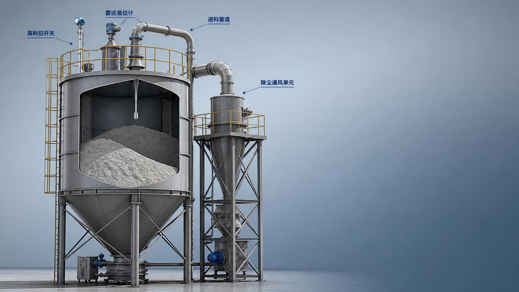
Level monitoring and overfill protection become necessary in dry bulk storage tanks as soon as the stored material can bridge, compact, fluidize, generate dust, or damage downstream equipment when the actual fill condition is misread. In technical terms, the need is not determined by tank size alone. It depends on material behavior, vessel geometry, filling rate, discharge pattern, and the consequence of a false level signal. A small day bin handling cement powder with pneumatic filling may require stricter protection than a larger tank storing a free-flowing granular product, because pressure pulses, dust concentration, and sudden filling surges can conceal the real headspace condition.
For storage used in grain, lime, fly ash, mineral powder, plastic pellets, carbon black, chemical intermediates, or blended dry additives, the first warning sign is usually process inconsistency rather than visible overflow. A tank may appear to have capacity remaining while material has already built a cone under the inlet, formed a stable arch, or packed against one sidewall. In those conditions, operators may continue feeding product until the roof load, venting system, filter unit, or inlet piping is exposed to stress beyond the intended operating range. Overfill protection is therefore tied to mechanical integrity as much as to inventory control.
Situations That Typically Require Dedicated Monitoring
Dry bulk storage tanks usually need continuous or point level devices when any of the following conditions exist: intermittent visual inspection is impossible, filling is automated, the material is dusty or opaque, the roof is closed, or the tank is tall enough that sounding methods are impractical. In indoor installations, enclosed transfer points and limited sight lines make manual verification unreliable. In outdoor installations, condensation, temperature variation, and vibration can interfere with assumptions based only on feeder runtime or truck delivery records.
A high fill rate is one of the clearest triggers. Pneumatic conveying can raise material level very quickly, especially in cement, fly ash, or fine mineral applications. Once the vessel nears the top, even a short delay in stopping the blower or rotary valve can send material into filter housings, pressure relief assemblies, or vent ducts. A slow-fed grain bin may give more response time, but if the bin has eccentric inlet loading or poor internal flow, a false low reading can still create an overfill event without any dramatic process alarm.
Another condition is when the stored solid has poor and changing flow characteristics. Moisture pickup, particle size variation, and compaction during transport can change how material settles in the tank. A powder received after long-distance trucking may enter as loose material but later cake near the wall. Pellets that normally flow well can hang up if fines accumulate. In these cases, a single low-cost point switch located in one spot may be insufficient because it confirms only local contact, not the overall surface profile.
Why Tank Design Changes the Monitoring Requirement
The shape and construction of dry bulk storage tanks strongly influence where measurement errors occur. In welded or bolted steel silos with steep conical hoppers, discharge may be mass flow or funnel flow depending on wall finish, hopper angle, and the friction properties of the product. Funnel flow tends to leave stagnant zones, so a sensor mounted above the outlet centerline may indicate an empty region while material remains packed around the perimeter. That matters for low-level alarms, but it also affects overfill logic because false assumptions about usable capacity encourage additional filling.
Roof structure also matters. Tanks with narrow roof access, multiple reinforcing members, or crowded nozzles may create dead zones for non-contact sensors. Radar, ultrasonic, and guided-wave devices each respond differently to internal obstructions, angled surfaces, dust plumes, and buildup. If the roof includes a central fill pipe and nearby filter receiver, the sensor beam can pick up false reflections unless the mounting nozzle, aiming angle, and blanking distance are chosen carefully.
Material of construction influences maintenance exposure. Carbon steel tanks used for cementitious materials often face abrasion at the inlet and coating buildup at the upper shell. Stainless or coated internals may be selected where contamination, corrosion, or aggressive chemicals are relevant. In every case, the sensor wetted parts, seal materials, and cable jackets need to match dust temperature, electrostatic conditions, and chemical compatibility. A level switch that works in a dry grain stream may not remain stable in hot ash or alkaline powder.
Where Simple Measurement Assumptions Fail
A common mistake is to assume that a level reading represents stored mass. Dry bulk storage tanks do not behave like water tanks. Bulk density can shift from load to load, and the angle of repose changes with moisture and fines content. A reading of 70 percent height does not necessarily mean 70 percent usable inventory. For process control this may be acceptable, but for overfill prevention the system should be based on the physical maximum safe fill point of the vessel, not on estimated tonnage alone.
Another frequent error is relying on delivery scheduling as protection. If truck discharge volumes are known, some sites assume the remaining tank capacity is known as well. That approach fails when previous withdrawals were inaccurate, when residual material remained bridged, or when the tank did not fully empty because of ratholing. A delivery can then exceed available volume even though paperwork suggests adequate space.
There is also a tendency to treat all high-level alarms as overfill protection. They are related but not identical. A process high-level alarm may warn that the tank is approaching a normal operating limit. An independent overfill device should sit at the maximum permissible level before material reaches vulnerable internals or vent paths, and it should trigger a clear action such as feed shutoff, divert logic, or upstream interlock. If both functions depend on the same instrument and that instrument drifts, both layers can fail together.
Choosing the Right Sensing Approach
The selection depends on whether the goal is trending inventory, confirming a transfer cut-off point, or preventing a hazardous overflow. Continuous measurement is often useful for planning and balancing storage, while point level switches provide discrete alarms at high-high or low-low positions. Many installations use both because the failure modes are different.
Radar is often chosen for tall tanks, dusty conditions, and applications where non-contact measurement reduces buildup problems on the sensor face. It can perform well in dry powders and granules, but internal obstructions, narrow nozzles, and low dielectric materials may require site-specific verification. Ultrasonic devices can be affected by heavy dust, temperature gradients, and angled surfaces, so they are less forgiving in dense pneumatic filling service.
Rotary paddle switches remain common for powders and granules because they are mechanically simple and easy to understand, though they need correct torque selection, insertion length, and mounting location. Vibrating probes may suit fine materials if buildup is controlled. Capacitive switches can work effectively, but the calibration margin must account for product variability and wall coating. Guided-wave radar may be used where the tank geometry makes free-space measurement difficult, although probe loading and abrasion need attention.
In some projects involving unusual geometry, split compartments, offset inlets, or mixed discharge requirements, design teams consider Custom Non-standard Silos and Storage Tanks because sensor placement, nozzle orientation, and maintenance access are easier to manage when the vessel layout reflects the real filling pattern rather than a generic shell drawing.
Overfill Protection Is a System, Not a Single Device
An effective arrangement usually includes the storage vessel, the filling equipment, the venting path, the alarm logic, and the shutdown response. If a high-high level switch trips but the screw conveyor, blower, bucket elevator, or diverter valve does not stop promptly, the protective intent is incomplete. Likewise, a stop signal that works in the control panel may still fail in practice if there is material already in transport line lag volume. Pneumatic systems can continue pushing solids after the feed command is removed, so the switch elevation must account for residual conveyed material.
Vent filters and pressure relief components need the same attention. In dry bulk service, some overfill events first appear as filter blinding, dust release around gaskets, or pressure fluctuation, not a visible spill from the roof. If the vessel is filled too high, product may strike the filter elements directly or enter spaces intended only for air handling. That can shorten filter life, disturb pressure balance, and leave hidden deposits that later harden.
Signal independence matters as well. Where the consequence of overfill is serious, it is prudent to separate the normal level indication from the final high-level trip by using different sensing principles or at least separate circuits and power paths. The purpose is to avoid a single blockage, calibration error, or wiring fault defeating both monitoring and protection at once.
Installation Details That Affect Reliability
Good devices perform poorly when mounted in the wrong place. A high-level switch directly under the fill stream may be struck by falling material, coated by dust, or triggered by a local pile while the rest of the tank still has space. Positioning slightly away from the main inlet can reduce this problem, but if the product forms asymmetric piles, that offset may create the opposite error. The mounting location should follow expected fill pattern, not only mechanical convenience.
Insertion length and nozzle stand-off are often overlooked. A switch buried inside a long nozzle may not contact product at the intended elevation. A radar installed in a nozzle that is too narrow or too tall may suffer false echoes. Flexible cable probes need enough clearance from ladders, braces, and walls. For tanks exposed to vibration, cable support and gland sealing deserve attention because intermittent electrical faults can imitate unstable process conditions.
Access for cleaning and proof testing should be considered before fabrication. A roof-mounted device that cannot be reached without extensive temporary access is less likely to be inspected at the interval the process actually needs. This becomes relevant in tanks storing sticky meal, damp powder, or products that generate top-side crusting. Even a robust instrument can become unreliable if buildup changes its sensing surface.
When Procurement and Installation Records Are Not Enough
Documentation showing that a sensor was ordered for a dry bulk storage tank does not confirm that the protection is adequate. The specification should match particle characteristics, temperature range, vessel pressure or vacuum exposure, hazardous area classification where applicable, cable routing, flange size, and expected cleaning method. A mismatch often appears when an instrument suited for free-flowing pellets is installed on cohesive powder, or when a standard gasket material is used where chemical dust attacks the seal.
Transport and erection can also alter performance. Long vessel sections may arrive with nozzle orientation changed for shipping practicality. During field assembly, a sensor port can end up too close to a handrail, vent body, or reinforcement rib. If the installation drawing is not rechecked against the actual tank roof layout, the device may meet the purchase order but still have an obstructed measuring path.
For non-standard process constraints, including unusual cone angles, retrofitted side nozzles, or limited headroom above the roof, some facilities evaluate Custom Non-standard Silos and Storage Tanks because the vessel arrangement itself may need adjustment before any level monitoring technology can perform consistently.
Maintenance Signals That Should Not Be Ignored
Erratic trend lines, repeated high-level trips during partial fills, and a need for frequent recalibration often point to a process issue rather than a defective instrument alone. Dust accumulation on the sensor face, condensation inside conduit, aeration from pneumatic filling, and changes in product blend can all distort readings. A maintenance response should therefore include inspection of the vessel interior condition, venting performance, and actual material flow pattern.
Proof testing should verify the real protective function, not only panel indication. That means confirming whether the switch changes state at the expected material level or simulated condition, whether the signal reaches the control logic correctly, and whether the filling equipment stops within the allowable time. If the system uses delayed shutdown, timer settings should reflect actual transfer lag rather than assumed values copied from another tank.
Where tanks alternate between products, cleaning residue can change the sensing threshold. Fine residual powder left after pellets, for example, may build on probes and create a false covered condition. The maintenance plan should reflect product changeover frequency, not only calendar intervals.
Practical Threshold for Deciding When Protection Is Needed
If a misread level can lead to dust release, structural loading at the roof, blockage of vent components, contamination from cross-filling, or interruption of a controlled feed process, dedicated level monitoring and overfill protection should be treated as part of the tank design basis. If the tank is filled automatically, remotely, rapidly, or without direct line of sight, that need becomes stronger. Where the stored material is cohesive, abrasive, low-density, moisture-sensitive, or electrostatically active, the monitoring method should be reviewed against those properties rather than selected as a standard accessory.
Dry bulk storage tanks operate safely when the instrument choice, mounting details, and shutdown logic reflect the real behavior of the stored solid. The point at which monitoring becomes necessary is usually earlier than expected, especially once process variability, transport lag, and false assumptions about usable volume are taken into account.
Related Posts
- ▶ How a Dry Bulk Silo Handles Pneumatic Filling and Gravity Discharge
- ▶ What Is a Dry Bulk Silo, and When Does a Factory Need One?
- ▶ Can dry bulk storage silos be integrated into existing PLC-controlled batching systems?
- ▶ Do dry bulk silos designed for API 650 compliance meet ASME Section VIII requirements?
- ▶ Is almacénamiento de sólidos a granel en silos de acero inoxidable viable for small-scale agrochemical distributors?
- ▶ How do vibration-based level sensors perform in stainless steel silos with powder coating?
Online Message