





How a Dry Bulk Silo Handles Pneumatic Filling and Gravity Discharge
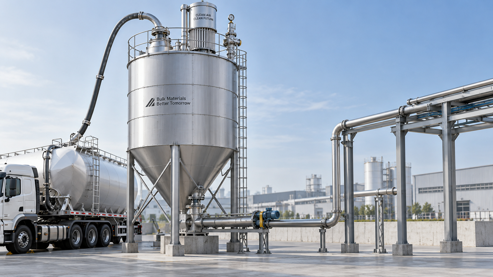
A tanker begins unloading, the conveying line pulses, and powder enters the silo faster than it appears to settle. At the roof, a vent filter releases conveying air while retaining dust. Below, the hopper must eventually deliver that same material at a predictable rate. These operations are connected: a filling arrangement that leaves material heavily aerated can change discharge behavior, while inadequate ventilation can threaten the structure during either operation.
A dry bulk silo therefore needs more than adequate storage capacity. For technical evaluators, the important questions concern airflow, pressure protection, material properties, hopper geometry, and control logic. Understanding the complete filling-to-discharge cycle makes it easier to assess a steel silo for grain, building materials, power-sector products, or chemicals—and to distinguish a workable design from one that merely has enough volume.
Follow the material—and the air
During pneumatic filling, a blower or compressed-air system transports bulk solids through a pipe into the silo. The material separates from the conveying air as velocity falls and particles settle. The air must then leave through a properly sized filtration system.
The incoming stream introduces two ventilation demands: conveying air entering with the solids, and air displaced by the accumulating material. The relative contribution of each depends on the conveying method, material bulk density, and filling rate. Filter selection should use the actual airflow at silo conditions, not an unconverted compressor rating expressed at reference conditions.
During gravity discharge, solids move toward the outlet under their own weight. Air must enter to replace the discharged volume, and air within the material may also move through the bed. Fine, low-permeability powders can respond quite differently from coarse granules. A silo that fills successfully may still discharge poorly if deaeration, incoming ventilation, or hopper flow has been overlooked.
The design boundary should cover the entire system: delivery equipment, filling pipe, silo shell and roof, filter, protective devices, hopper, outlet feeder, and downstream equipment. Evaluating these items independently leaves important interfaces unresolved.
Pneumatic filling: separating normal ventilation from pressure protection
The vent filter carries the routine airflow
The silo vent filter is the normal escape route for conveying air. Its required filtration area depends on airflow, dust loading, particle characteristics, filter media, and cleaning method. Fine cement, fly ash, and chemical powders may present very different filtration challenges even when their nominal filling rates are similar.
Assess filter performance under realistic conditions, including moisture exposure and the expected condition between cleaning cycles. A filter sized only for clean-media operation can become a bottleneck after dust accumulates. Differential-pressure monitoring helps reveal increasing resistance, but it does not replace direct silo-pressure measurement: filter pressure drop and internal silo pressure describe different conditions.
Pulse-cleaning systems also require dependable compressed air, suitable air quality, and accessible maintenance arrangements. When cleaning fails, dust buildup can progressively reduce vent capacity. Where recovered dust returns to the silo, the arrangement should prevent accumulation around the filter interface and allow inspection without unsafe access.
A pressure-relief device is not an extra vent
Many atmospheric storage silos tolerate only limited positive and negative pressure. They should not be treated as pressure vessels simply because pneumatic conveying is used. The conveying line may operate at a pressure far above the silo’s allowable internal pressure.
A pressure/vacuum relief device protects against abnormal conditions; it should not routinely open during filling. Repeated lifting indicates a problem such as excessive airflow, a restricted filter, or unsuitable controls. Relief capacity, opening settings, and installation must be coordinated with the silo’s allowable pressure and credible fault scenarios.
Vacuum protection matters as well. Restricted air admission during discharge can create inward loading on the shell or roof. The appropriate protection may involve a dedicated vacuum-relief function rather than assuming the filtration path always admits sufficient air.
Stopping delivery requires more than an alarm
A high-level alarm tells an operator that capacity is running out. An independent high-high level function can initiate a protective filling shutdown. A separate high-pressure function may also be required, depending on the risk assessment. The effectiveness of either depends on what happens after the signal is generated.
Closing a silo inlet valve does not instantly remove the material and compressed air already in the conveying line. It can also create an upstream blockage or overpressure if the conveying source continues operating. A coordinated shutdown should define how the blower or tanker supply stops, how line isolation occurs, and how residual pressure is managed.
For tanker deliveries, confirm compatible connections and shutdown interfaces before commissioning. Near the end of unloading, reduced solids loading and continued air delivery can expose the vent system to demanding conditions. Vent capacity must cover the agreed delivery envelope, not just an average unloading rate.
Why gravity discharge depends on tested flow properties
Gravity provides the driving force, but it does not guarantee reliable flow. A material described as “dry” may still be cohesive, moisture-sensitive, or prone to caking. Fine powders can gain strength during storage; some granules interlock; aerated powders can flow too freely once the outlet opens.
Useful characterization goes beyond particle size and loose bulk density. Depending on the product, evaluation should include cohesive strength, wall friction against the proposed contact surface, compressibility, permeability, and changes caused by storage time, temperature, or moisture. Shear testing provides a stronger basis for hopper design than visual observation or angle of repose alone.
Mass flow can improve inventory turnover and reduce stagnant regions, but it is not achieved simply by specifying a steep cone. Hopper shape, wall material, surface condition, and outlet size work together. Hopper-angle values are also meaningless unless the specification states whether the angle is measured from horizontal or vertical.
The feeder below the hopper is equally important. A screw feeder that extracts mainly from one end of a long outlet can create inactive regions even where the hopper geometry otherwise supports mass flow. The extraction arrangement should activate the intended outlet area rather than undermine it.
The transition after filling is often where problems appear
A freshly filled powder may contain substantial entrained air. Its apparent bulk density can be lower than its settled density, and its discharge behavior can change as it deaerates. Opening the outlet immediately may cause flushing—an uncontrolled surge of aerated powder—rather than a steady gravity-fed stream.
For sensitive products, evaluate whether a settling interval, controlled startup sequence, or suitable feeder is necessary. A slide gate provides isolation but is not automatically an effective metering device. Rotary valves and screw feeders can regulate withdrawal, although leakage, wear, pressure differences, and product behavior must be considered.
Flow aids require the same care. Aeration pads can help some powders move but may worsen flushing or introduce unsuitable air. Vibrators can assist certain materials, yet poorly selected vibration can consolidate others or create fatigue concerns at attachments. Neither is a universal substitute for correct hopper and outlet design.
For grain, pneumatic handling may require attention to kernel damage and segregation. Cementitious materials raise concerns about fine dust and moisture-driven buildup. Fly ash characteristics can vary with source and conditioning. Chemical products may require compatibility checks, corrosion provisions, or a different conveying atmosphere. The material name alone is not a sufficient design specification.
Structural design and safety standards must match the duty
Stored solids do not load a silo like water in a tank. Wall friction, filling pattern, discharge pattern, and eccentric withdrawal affect the pressures acting on the structure. A structural assessment must address relevant filling and discharge cases, along with equipment loads, wind, seismic effects, and internal pressure or vacuum where applicable.
In projects using European design frameworks, EN 1991-4 addresses actions on silos and tanks, while EN 1993-4-1 addresses steel silo structural design. Other jurisdictions use different standards and approval routes. The applicable framework should be established early, rather than assembled after fabrication.
Combustible dust requires a separate hazard assessment. Grain dust and some chemical powders can present explosion risks; other bulk materials may not. Applicable requirements may include NFPA 660 or relevant European explosion-safety provisions, depending on location and duty. Grounding, ignition control, explosion protection, and isolation must follow the assessed hazard.
Pressure relief for conveying faults is not explosion protection. A conventional silo pressure/vacuum relief valve should not be assumed to provide explosion venting. Likewise, normal pneumatic-filling controls do not resolve the consequences of a dust explosion or its propagation through connected equipment.
What to request in a technical proposal
A useful proposal makes assumptions visible. For a custom steel silo, ask the supplier to state the material data used, the pneumatic delivery envelope, the proposed flow regime, and the permissible operating conditions. Equipment ratings without a common design basis are difficult to compare.
- Storage basis: usable volume, bulk-density range, operating levels, and freeboard allowance.
- Filling basis: solids throughput, maximum airflow at stated conditions, delivery pressure, and expected shutdown behavior.
- Ventilation and protection: filter duty, monitoring, relief sizing, allowable silo pressures, and inspection access.
- Discharge basis: flow-test evidence, hopper geometry, outlet dimensions, feeder capacity, and downstream pressure conditions.
- Controls: cause-and-effect logic for high level, high pressure, filter faults, and unavailable downstream equipment.
- Verification: structural design basis, commissioning procedures, maintenance requirements, and documented limitations.
Shandong Guokai International Trade Co., Ltd. integrates steel silo development, manufacturing, and sales for sectors including grain, building materials, electric power, and chemicals. For projects requiring application-specific geometry or interfaces, its Custom Non-standard Silos and Storage Tanks provides a relevant starting point for discussion. The technical brief should distinguish dry-solids storage requirements from liquid-tank requirements; customization does not remove the need for verified airflow, flow behavior, and structural calculations.
Commission the cycle, not just the vessel
Before handover, verify sensor operation, filter cleaning, relief-device condition, shutdown interfaces, and outlet equipment. Test protective logic through controlled simulations where appropriate, rather than deliberately overpressurizing the silo.
Trial filling and discharge should stay within an approved operating envelope. Record silo pressure, filter differential pressure, delivery behavior, discharge stability, and remaining inventory. Where storage time changes material behavior, immediate discharge alone cannot demonstrate long-term reliability.
The strongest dry bulk silo design is one in which normal operation is predictable and abnormal conditions have defined responses. Air leaves safely during filling, solids move reliably during discharge, and the controls recognize when either process is departing from its design limits. That coordinated performance—not capacity alone—is the basis for a sound technical decision.
Related Posts
- ▶ How a Dry Bulk Silo Handles Pneumatic Filling and Gravity Discharge
- ▶ What Is a Dry Bulk Silo, and When Does a Factory Need One?
- ▶ Can dry bulk storage silos be integrated into existing PLC-controlled batching systems?
- ▶ Do dry bulk silos designed for API 650 compliance meet ASME Section VIII requirements?
- ▶ Is almacénamiento de sólidos a granel en silos de acero inoxidable viable for small-scale agrochemical distributors?
- ▶ How do vibration-based level sensors perform in stainless steel silos with powder coating?
Online Message