





Cement Silo Pressure Relief Systems Explained
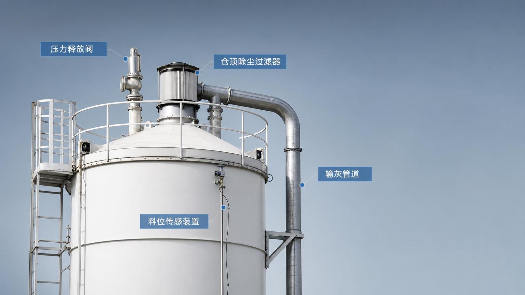
Cement Silo Pressure Relief Systems Explained
In bulk material storage, a reliable cement silo pressure relief system is essential for protecting equipment, maintaining safe operating conditions, and ensuring efficient dust control.
Understanding how it works makes technical review much more practical. It helps identify real operating risks, not just theoretical design points.
A cement silo often looks simple from the outside. In reality, pressure behavior inside the vessel can change very quickly during filling, aeration, and filter malfunction.
That is why a pressure relief system is not a secondary accessory. It is a core safety and performance component in any modern cement silo installation.
Why Pressure Builds Inside a Cement Silo
Pressure in a cement silo usually rises during pneumatic loading. Large volumes of conveying air enter with the cement and must exit in a controlled way.
If that air cannot escape fast enough, internal pressure increases. Even a short pressure spike can overstress the silo roof, seams, or dust collector.
Negative pressure can also become a problem. During discharge or sudden airflow changes, the cement silo may experience partial vacuum conditions.
Both overpressure and vacuum matter. A complete pressure relief system must address each condition, especially in enclosed or high-throughput storage operations.
In actual projects, pressure issues often trace back to system interaction. The blower rate, pipe diameter, filter area, and loading speed all influence the result.
What a Cement Silo Pressure Relief System Actually Does
The basic job is straightforward. The system releases excess internal pressure before the structure or connected equipment reaches a damaging level.
It also helps stabilize airflow through the filter unit. That improves dust retention and supports cleaner plant operation during cement transfer.
A well-designed cement silo pressure relief system usually performs four functions:
- limit positive pressure during filling;
- limit vacuum during discharge or pulse cleaning;
- protect the dust collection system from overload;
- reduce the chance of structural distortion or dust leakage.
This also affects maintenance cost. When pressure remains within design limits, filters, seals, and welded joints usually last longer.
Main Components in a Modern Cement Silo Setup
Most cement silo pressure relief systems combine several parts. Each one handles a different piece of airflow management and equipment protection.
Pressure Relief Valve
This is the primary protective device. It opens when internal pressure exceeds the preset value and closes after conditions normalize.
Good valve response matters more than appearance. A slow or sticking valve can allow a dangerous pressure peak inside the cement silo.
Vacuum Relief Function
Many units are dual acting. They release excess positive pressure and admit air under vacuum conditions to protect the vessel shell.
That matters in taller storage systems where discharge rates can shift rapidly. Thin plate areas are especially sensitive to vacuum deformation.
Dust Collector or Silo Top Filter
The filter separates air from cement dust during filling. When it performs poorly, pressure inside the cement silo rises much faster.
Pulse jet cleaning, cartridge condition, and filter area all influence relief valve performance. These parts should always be evaluated together.
Level Sensors and Control Interlocks
Overfilling can choke ventilation paths. High-level alarms and loading interlocks reduce the chance of forcing air through blocked material space.
In practical terms, pressure protection works better when it is part of a broader control strategy, not an isolated mechanical device.
How Pressure Relief Systems Are Evaluated
A technical review should move beyond product catalog claims. The key question is whether the system matches the actual loading and discharge conditions.
Several points deserve close attention during cement silo assessment:
- Set pressure and vacuum values must fit the structural design limits.
- Airflow capacity must exceed the peak conveying air volume.
- Valve opening response should remain consistent after repeated cycles.
- The filter system must handle dust load without rapid clogging.
- Maintenance access should be practical for inspection and cleaning.
Standards and local codes also matter. Pressure relief design should align with the project’s applicable structural, environmental, and process requirements.
From a procurement perspective, documented testing is a strong signal. Reliable suppliers usually provide opening pressure data, material details, and installation guidance.
Common Failure Modes and What They Reveal
When a cement silo pressure relief system fails, the cause is often predictable. The warning signs usually appear well before major structural damage.
- Dust discharge from unexpected points may indicate blocked filtration or leaking seals.
- Roof deformation often suggests repeated overpressure events.
- Slow discharge can point to vacuum imbalance or aeration issues.
- Frequent valve activation may mean the filter is undersized or poorly maintained.
- Corrosion or material buildup can prevent proper valve movement.
These issues are not only maintenance concerns. They also reveal whether the original cement silo design allowed enough margin for real operating conditions.
This is especially important in high-capacity storage. Larger installations amplify pressure imbalance because loading rates and air volumes scale quickly.
For example, large-volume solutions such as 1500-3000 Tons Silos require matched pressure relief, filtration, and structural detailing.
Selection Factors for Long-Term Reliability
Choosing a cement silo pressure relief system should start with process data, not only silo size. Airflow and material behavior drive the real requirement.
Important selection factors include:
- cement loading method and blower pressure;
- peak transfer rate and expected loading duration;
- silo geometry, roof strength, and shell thickness;
- ambient humidity, temperature, and corrosion exposure;
- maintenance frequency and spare part availability.
Material compatibility also deserves attention. Cement dust is abrasive, and outdoor installations face weather cycles that affect sealing and moving parts.
It is usually better to review the pressure relief valve and filter as one package. That approach gives a more realistic view of system performance.
Manufacturers with strong silo engineering capabilities often handle this integration more effectively. That reduces mismatches between storage volume, airflow, and structural loading.
Installation and Maintenance Points That Matter
Even a high-quality cement silo pressure relief system can underperform if installation details are ignored. Field execution has a direct impact on safety.
The valve should be mounted correctly, sealed properly, and kept free from hardened dust accumulation. Access for inspection should be simple and safe.
Routine checks should cover opening movement, gasket condition, fastener integrity, and filter cleaning effectiveness. These are small tasks with large consequences.
A practical maintenance rhythm usually includes:
- visual checks before heavy loading periods;
- scheduled inspection of filter elements and pulse systems;
- recording abnormal pressure events or dust emissions;
- replacement of worn seals and damaged moving parts.
Where large storage capacity is planned, such as 1500-3000 Tons Silos, maintenance planning should be defined early, not after commissioning.
A Practical View for Technical Decision-Making
A cement silo pressure relief system should be judged by performance under real loading conditions. Catalog parameters alone do not tell the whole story.
The most useful review combines structural limits, conveying airflow, dust control efficiency, and maintenance practicality. That is where reliable long-term operation starts.
For any cement silo project, a properly matched relief system protects the vessel, supports compliance, and reduces avoidable operating disruptions.
When comparing suppliers or project options, focus on tested relief performance, filter coordination, and documented engineering support. Those details usually separate durable systems from costly problems.
Related Posts
- ▶ How a Dry Bulk Silo Handles Pneumatic Filling and Gravity Discharge
- ▶ What Is a Dry Bulk Silo, and When Does a Factory Need One?
- ▶ Can dry bulk storage silos be integrated into existing PLC-controlled batching systems?
- ▶ Do dry bulk silos designed for API 650 compliance meet ASME Section VIII requirements?
- ▶ Is almacénamiento de sólidos a granel en silos de acero inoxidable viable for small-scale agrochemical distributors?
- ▶ How do vibration-based level sensors perform in stainless steel silos with powder coating?
Online Message